There are three classes of widely used IIR (recursive) filters in signal processing: Butterworth, Chebyshev, and elliptical. In this article I will discuss the Butterworth filter and provide example code implementing and using the filter. The Chebyshev and elliptical filters will be discussed in follow up articles.
Butterworth filters are desirable for their ease of implementation, good phase response, and their smooth monotonic frequency response in both the pass-band and the stop-band. However they don’t achieve the steep roll-off of Chebyshev filters, but Chebyshev filters achieve this steeper roll-off by allowing either some ripple in the pass-band (type 1) or the stop-band (type 2). The type 2 Chebyshev filters are rarely used so only type 1 Chebyshev filters will be discussed in follow up articles. The elliptical filters strike a balance between the type 1 and type 2 Chebyshev filters by allowing ripple in both the stop and pass-bands while achieving the steepest roll-off gain of all three filter types. Wikipedia has excellent overview articles discussing the Butterworth, the Chebyshev, and the elliptical filters, so I’ll refer you to those articles for a thorough background treatment of each filter type instead of repeating that information here.
Butterworth Filters
Butterworth filters exhibited a ripple free frequency response with a -20*n Db/decade roll-off at the cutoff frequency, where n is the order of the filter. There are only three design parameters for a Butterworth filter, the order n, the cut-off frequency  , and the DC gain,
  , or the gain at zero frequency. So the gain of any Butterworth filter can be written in terms of these three parameters.
Engineers typically think in terms of Hertz, so we can relate the linear frequency cutoff we are accustom to, to the angular frequency we have above, with the familiar equation,  . Now rewriting the above equation in terms of frequency we have:
The Butterworth Filter in C#
To digitally implement a Butterworth filter in code, we work in the frequency domain (for performance reasons), following the three steps outlined in the pseudo code below.
function ButterworthFilter
{
  fftSignal = FFT( signal );

  // Scale FFT by butterworth gain
  for( int w = 0; w < N/2; w++)
    filteredSignal[w] = fftSignal[w] * butterworthGain[w];

  return inverseFFT( filteredSignal );
}
Given the dual relationship between convolution and multiplication in the time and frequency domains, we could equally well implement this filter by convolving in the time domain the inverse fourier of the Butterworth's frequency response with the signal, but this would require O(n*n) time. By using the FFT, and working in the frequency domain, we achieve the same effect in O(n* log(n)) time, where n is the length of the signal to be filtered.
DoubleComplexVector ButterworthFilter( DoubleComplexVector signal,
   double sampleFrequency, int order, double f0, double DCGain )
    {

      var N = signal.Length;

      // Apply forward FFT
      var fft = new DoubleComplexForward1DFFT( N );
      var signalFFT = fft.FFT( signal );

      if ( f0 > 0 )
      {

        var numBins = N / 2;  // Half the length of the FFT by symmetry
        var binWidth = sampleFrequency / N; // Hz

        // Filter
        System.Threading.Tasks.Parallel.For( 1, N / 2, i =>
        {
          var binFreq = binWidth * i;
          var gain = DCGain / ( Math.Sqrt( ( 1 +
                        Math.Pow( binFreq / f0, 2.0 * order ) ) ) );
          signalFFT[i] *= gain;
          signalFFT[N - i] *= gain;
        } );

      }

      // Reverse filtered signal
      var ifft = new DoubleComplexBackward1DFFT( N );
      ifft.SetScaleFactorByLength(); // Needed to get the correct amplitude
      signal = ifft.FFT( signalFFT );

      return signal;
   }
This general Butterworth filtering code begs a bit of explanation. The FFT provides the Fourier transform for N/2 positive frequencies, and symmetrically (via a complex conjugation) for N/2 negative frequencies. Because of this we can loop just N/2 times scaling the symmetric halves simultaneously by our Butterworth gain in our Parallel.For loop for improved performance. When scaling the FFT by the gain of the Butterworth filter, we must know the angular frequency of each bin we scale, which is captured by the binFreq variable; recalling that the frequency resolution of a length N FFT is ( Fs / N / 2 ) Hz, where Fs is the sampling frequency.
Although this code will execute very efficiently it can be significantly optimized if it is specialized to filtering only signals of a fixed length and fixed sampling frequency - a very common situation in many systems. In this case the Butterworth gains can all be computed ahead, avoiding the expensive Math.Sqrt() calls, also the NMath FFT classes would only need to be created once outside the filtering routine. Finally we could do all of the computation in-place and eliminate the copy to a new result vector, with:
   ...
   // Apply forward FFT in place
   var fft = new DoubleComplexForward1DFFT( N );
   fft.FFTInPlace( signal );
   ...
Filtering Example
To test our new Butterworth filter, I generated a test signal which is simply the sum of two sinusoids of frequencies 1 Hz and 8 Hz. This continuous signal is then sampled at 25 Hz and filtered with a third order Butterworth filter using a cut-off frequency of 1.5 Hz and a DC gain of one. Finally, a chart is generated of the input signal and of the filtered signal to visualize the action of the filter in the time domain.
    public void FilterTest()
    {
      var signal = new DoubleComplexVector( 100 );

      var Fs = 25; // Sample rate, 25Hz
      var f1 = 1; // 1 Hz Signal
      var f2 = 8; // 8 Hz Signal
      for ( int t = 0; t < 100; t++ )
      {
        signal[t] = new DoubleComplex( Math.Sin( 2 * Math.PI * f1 / Fs * t ) +
                    Math.Sin( 2 * Math.PI * f2 / Fs * t ), 0.0 );
      }

      // Filter
      var filteredSignal = ButterworthFilter( signal, 25, 3, 1.5, 1.0 );

      // Display results
      var chart = NMathChart.ToChart( new DoubleVector( signal.ToRealDataTable() ) );
      chart.Titles[0].Text = "Input signal, sampled at 25 Hz";
      chart.ChartAreas[0].AxisY.Title = "Input signal magnitude";
      var chartfft = NMathChart.ToChart( new DoubleVector( filteredSignal.ToRealDataTable() ) );
      chartfft.Titles[0].Text = "Filtered signal";
      chartfft.ChartAreas[0].AxisY.Title = "Filtered signal magnitude";

      List charts = new List() { chart, chartfft };

      var compositeChart = NMathChart.Compose( charts, 1, 2, NMathChart.AreaLayoutOrder.ColumnMajor );
      compositeChart.Width = 650;
      compositeChart.Height = 300;
      NMathChart.Show( compositeChart );

    }
This example code generates the following composite chart showing on the left the unfiltered signal, and on the right the filtered signal.
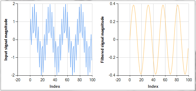
As expected, almost all of the high frequency sinusoid at 8Hz has been eliminated from the original signal. In this case where the 'noisy' 8 Hz signal is well separated from our 1Hz signal, the Butterworth filter does an excellent job. The next signal processing blog entry will cover the Chebyshev type 1 filter.
-Happy Computing,
Paul Shirkey
Please contact us at sales@centerspace.net with any questions you may have.
how can i implement such a filter as bandpass filter
The low-pass gain expression for Butterworth filters can be converted to a high-pass filter by inverting the “f \ f_c” axis. In other words, by replacing “f \ f_c” with “f_c \ f”. Now a bandpass filter can be created by running a high-pass filter in series with a low-pass filter. The pass-band width of your band-pass filter will be f_c_low – f_c_high. If this isn’t clear, a couple of sketches of the frequency responses of high and low pass filters overlaid on one another will probably clarify things.
can i use this code in my C# project ?
does it require library ?
thanks
Yes, it requires NMath. Please try our 30-day free evaluation.
– Trevor
so it seems it will work if i get NMath library ??
can you give me the link to get it ?
Here you go… http://centerspace.net/downloads/trial-versions/
sorry for bothering you ?
is there any way to implement the bandpass filter without the need of this library ..
I’m a student and working on my graduation project:(
can you help me ;(
its too expensive 🙁
You can use it for free for 30 days. If that doesn’t work, email at sales@centerspace.net and we will arrange an extension.
Alternatively, you can purchase a student edition for $99. Good luck!
Hello Sir,
Can you please let me know the format of “signal” to be passed for “DoubleComplexVector signal” in above program ?
I am triying it by giving input signal as .wav signal.
Please confirm our understanding.
Awaiting your reply. 🙂